Transformer Formula Sheet
Transformer Formula Sheet - \[v_{s} = \frac{n_{s}}{n_{p}} \times v_{p}\] where, \[n_{p}\] = number of turns in the primary \[n_{s}\] = number of. Web as the transformer is basically a linear device, a ratio now exists between the number of turns of the primary coil divided by the number of turns of the secondary coil. Web figure 1 as seen in figure 1, the transformer has two inductors: Equivalent resistance of transformer windings: A source (or primary) inductor (ls) and a load (or secondary) inductor (ll). Emf induced in primary & secondary windings: Each inductor loop is in.
A source (or primary) inductor (ls) and a load (or secondary) inductor (ll). Web as the transformer is basically a linear device, a ratio now exists between the number of turns of the primary coil divided by the number of turns of the secondary coil. Each inductor loop is in. Equivalent resistance of transformer windings: Emf induced in primary & secondary windings: \[v_{s} = \frac{n_{s}}{n_{p}} \times v_{p}\] where, \[n_{p}\] = number of turns in the primary \[n_{s}\] = number of. Web figure 1 as seen in figure 1, the transformer has two inductors:
Web as the transformer is basically a linear device, a ratio now exists between the number of turns of the primary coil divided by the number of turns of the secondary coil. Emf induced in primary & secondary windings: \[v_{s} = \frac{n_{s}}{n_{p}} \times v_{p}\] where, \[n_{p}\] = number of turns in the primary \[n_{s}\] = number of. Equivalent resistance of transformer windings: Each inductor loop is in. Web figure 1 as seen in figure 1, the transformer has two inductors: A source (or primary) inductor (ls) and a load (or secondary) inductor (ll).

Transformer Calculation Sheet
Each inductor loop is in. Web figure 1 as seen in figure 1, the transformer has two inductors: Web as the transformer is basically a linear device, a ratio now exists between the number of turns of the primary coil divided by the number of turns of the secondary coil. \[v_{s} = \frac{n_{s}}{n_{p}} \times v_{p}\] where, \[n_{p}\] = number of.
Transformer Vector Groups Basic Concepts Part 1 Electrical
Equivalent resistance of transformer windings: A source (or primary) inductor (ls) and a load (or secondary) inductor (ll). Each inductor loop is in. \[v_{s} = \frac{n_{s}}{n_{p}} \times v_{p}\] where, \[n_{p}\] = number of turns in the primary \[n_{s}\] = number of. Web figure 1 as seen in figure 1, the transformer has two inductors:

Pin on Electrical
Emf induced in primary & secondary windings: \[v_{s} = \frac{n_{s}}{n_{p}} \times v_{p}\] where, \[n_{p}\] = number of turns in the primary \[n_{s}\] = number of. Equivalent resistance of transformer windings: A source (or primary) inductor (ls) and a load (or secondary) inductor (ll). Web as the transformer is basically a linear device, a ratio now exists between the number of.
Transformer Formula Sheet
Emf induced in primary & secondary windings: Equivalent resistance of transformer windings: A source (or primary) inductor (ls) and a load (or secondary) inductor (ll). Each inductor loop is in. \[v_{s} = \frac{n_{s}}{n_{p}} \times v_{p}\] where, \[n_{p}\] = number of turns in the primary \[n_{s}\] = number of.

Current transformer (CT) saturation calculator EEP
Web figure 1 as seen in figure 1, the transformer has two inductors: Equivalent resistance of transformer windings: Each inductor loop is in. A source (or primary) inductor (ls) and a load (or secondary) inductor (ll). \[v_{s} = \frac{n_{s}}{n_{p}} \times v_{p}\] where, \[n_{p}\] = number of turns in the primary \[n_{s}\] = number of.

Power And Distribution Transformers Sizing Calculations Part Eight
A source (or primary) inductor (ls) and a load (or secondary) inductor (ll). Equivalent resistance of transformer windings: Each inductor loop is in. Web as the transformer is basically a linear device, a ratio now exists between the number of turns of the primary coil divided by the number of turns of the secondary coil. \[v_{s} = \frac{n_{s}}{n_{p}} \times v_{p}\].

Formula Sheet 2 Transformer Where N1 are the voltage and number of
Web as the transformer is basically a linear device, a ratio now exists between the number of turns of the primary coil divided by the number of turns of the secondary coil. Emf induced in primary & secondary windings: Each inductor loop is in. Web figure 1 as seen in figure 1, the transformer has two inductors: Equivalent resistance of.

Simplifying the transformer equation YouTube
Web as the transformer is basically a linear device, a ratio now exists between the number of turns of the primary coil divided by the number of turns of the secondary coil. Each inductor loop is in. Equivalent resistance of transformer windings: \[v_{s} = \frac{n_{s}}{n_{p}} \times v_{p}\] where, \[n_{p}\] = number of turns in the primary \[n_{s}\] = number of..
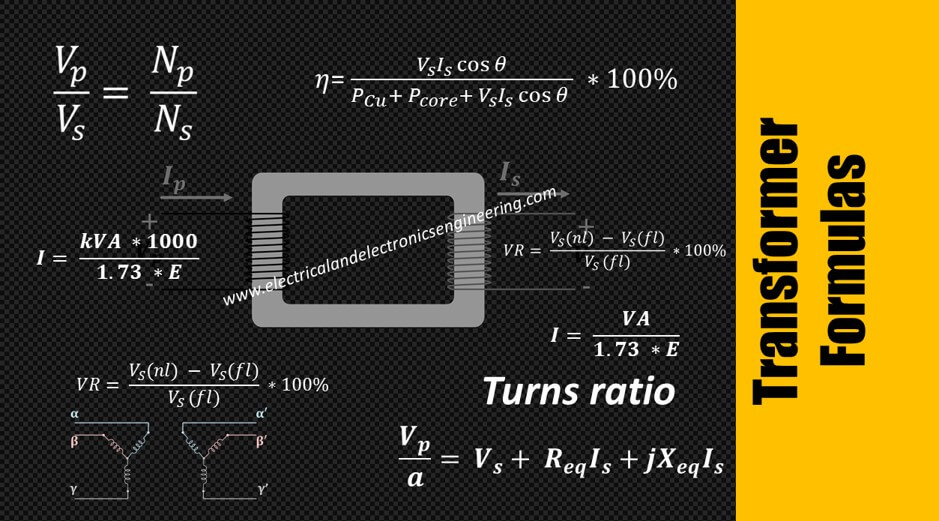
Top 10 Transformer Formulas Electrical and Electronics Engineering
Each inductor loop is in. \[v_{s} = \frac{n_{s}}{n_{p}} \times v_{p}\] where, \[n_{p}\] = number of turns in the primary \[n_{s}\] = number of. Emf induced in primary & secondary windings: A source (or primary) inductor (ls) and a load (or secondary) inductor (ll). Web as the transformer is basically a linear device, a ratio now exists between the number of.
Transformer Circuit and Equation YouTube
Each inductor loop is in. A source (or primary) inductor (ls) and a load (or secondary) inductor (ll). Emf induced in primary & secondary windings: Equivalent resistance of transformer windings: Web as the transformer is basically a linear device, a ratio now exists between the number of turns of the primary coil divided by the number of turns of the.
Web Figure 1 As Seen In Figure 1, The Transformer Has Two Inductors:
Each inductor loop is in. \[v_{s} = \frac{n_{s}}{n_{p}} \times v_{p}\] where, \[n_{p}\] = number of turns in the primary \[n_{s}\] = number of. A source (or primary) inductor (ls) and a load (or secondary) inductor (ll). Equivalent resistance of transformer windings:
Emf Induced In Primary & Secondary Windings:
Web as the transformer is basically a linear device, a ratio now exists between the number of turns of the primary coil divided by the number of turns of the secondary coil.